Fluid power has become a vital component in our ability to perform work: it harvests our crops, takes our waste to the landfill, moves the landing gear, entertains and protects us, and all with a power density and flexibility that is unmatched in any other power transfer system. However, when it comes to efficiency, fluid power systems are not very high on the list. This article series will ask us to think differently about our fluid power systems. We will look at energy in a different way and discover ways to transform fluid power energy to make our systems more efficient, and then be able to make better use of the new and improved components available to us.
Choose the best answer. Torque describes
a. Effort
b. Work
c. Power
d. All of the above
The answer is “a.” Torque is simply rotational force or effort. Work is effort over distance. Power is effort over distance in a specific time period. All of the above is, well, just another wrong answer. This distinction is important as we move forward in our understanding of energy usage with fluid power. Putting in a good effort is not the same as actually finishing the task and is a waste of energy. Putting in too much effort is also a waste of energy. In our fluid power systems, we want to provide just the right amount of effort to get the job done without waste. When we do not apply enough force to move a load, or when we intentionally stall a motor or clamp with a cylinder, effort is being applied but no work is being done. In a hydraulic system where pressurized fluid continues to be directed toward the load, its energy will be converted to heat, either across a relief valve or through the case drain of a pressure-compensated pump.
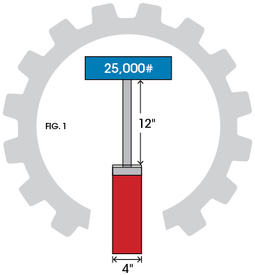
 I have a little formula for you to work out. To the right, we have a 4″ bore, hydraulic cylinder supporting a weight of 25,000 pounds at a 12″ extension (Fig. 1). What is the potential energy in lb-in of the load?
Well let’s see… we have a weight of 25,000 pounds lifted 12″, so we have 25,000 times 12″, which equals 300,000 lb-in for the potential energy.
Ok, now calculate the pressure and the volume of fluid in the cylinder. We divide the weight of 25,000 pounds by the piston area of 12.57 in2 and we find a pressure of about 1989 psi. We then find the volume by multiplying the area by the stroke, and we find we have a volume of about 151 in3. If we do not do any rounding off, when we multiply the volume of fluid by the pressure, we get exactly 300,000 lb-in.
For many of us, this is no surprise. But we need to think a little differently. By applying this load to the fluid, we have given each cubic inch a charge of 1989 pounds; each cubic inch has a potential energy of 1989 lb-in.
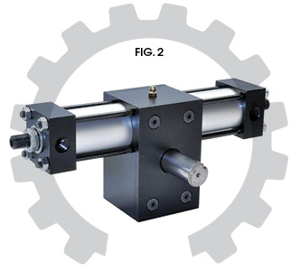
We will use this system as a weighted accumulator to move a rotary actuator (Fig. 2). The cylinder has a 1.128″ bore (for an easy area of 1 in2) and a 3″ stroke. The pinion gear has a 2″ pitch line diameter. The torque required for clockwise rotation is 1900 in-lb. For the counterclockwise rotation, the torque requirement is 1000 in-lb. We want it to fully rotate in each direction in one second.
We know that hydraulic fluid is relatively incompressible, and so we know that we will need a total of 3 cubic inches of fluid to rotate in each direction. So, how much potential energy will each cubic inch need in order to rotate clockwise? The pinion gear has a pitch line radius of 1 inch, and so to develop 1900 in-lb of torque, it will need 1900 pounds of force from the 1-in2 piston, or 1900 psi. The potential energy required for each cubic inch is 1900 lb-in. Using the same process for the counterclockwise rotation, we see that each cubic inch will need 1000 pounds of stored energy.
If we were to expose the potential energy from the accumulator directly to one side for clockwise rotation, another law of physics reminds us that the load will have an acceleration rate of 33.7, making the rotation occur in 0.122 seconds. The counterclockwise rotation will have an acceleration rate of 64 and will occur in 0.088 seconds.
So what do we do? Of course! We add flow controls. We call them flow controls, but they are actually power controls; they limit the rate of energy flow to the actuators. We have too much energy available, but we need the volume to extend the loads. The flow controls stand between the energy source and the cylinders to limit the power input.
 Now, this wouldn’t be so bad if the power controllers actually did something useful with the extra energy. But this is not the case. The power controllers simply discard the energy as heat. A needle valve, a pressure-compensated flow control, or a pressure-reducing valve all do the same thing; they peel off energy and disperse it as heat.
In this application, the energy stored in just 2.87 of the cubic inches would be enough to move the load clockwise. It would take the energy in just 1.51 cubic inches to satisfy the counterclockwise requirements. The total energy requirement could be satisfied with only 4.38 cubic inches, but, because we needed the volume, we used up 6 cubic inches and tossed the excess energy away. We used 11,934 lb-in of effort to do 8700 lb-in of work. As a result, 37% was given up as heat.
I am using this example to help us think differently about all our systems. We need to consider volume and pressure together as energy units, and flow and pressure together as units of power. We can then calculate the energy units needed to get a job done and compare that to what we actually use. Accumulators are often rightly used to reduce power requirements, and, when correctly used, are energy savers. But we need to understand the hidden waste as the excess potential energy is discarded. The weighted accumulator in this circuit stores enough fluid to cycle the rotary actuator 25 times, proving it to be an excellent storage device. However, the amount of energy stored could cycle the actuator 34 times. The problem is not with our storage system; it is with our process of controlling the energy as we release it.
This is not to single out accumulators as having a unique problem. If we use a pressure-compensated pump set at 1989 psi to supply these functions, the flow controls would still have to extract the extra energy and there would be additional loss through the case drain. A load-sensing pump, compensating at 200 psi above the load, would be an improvement, but still a substantial waste of energy. The point is this: when we push fluid against a resistance, we charge the fluid with energy, whether it is for storage in an accumulator or for immediate use. That energy is then conveyed by the fluid to the work site. Any energy in excess of what is needed to do the work has to be removed and is lost as heat. As long as we continue to think about flow and pressure as separate entities in our design process, we will have difficulty in finding a solution to what we may think are inherent energy issues when using fluid power.
In our pneumatic systems, we waste energy in different ways. We store the energy in a receiver just as with a hydraulic accumulator. If we did the same analysis of the energy stored, we would find the potential energy to be the pressure times the cubic inches of compressed air. What would be the potential energy in a one-gallon receiver charged to 120 psi? Well, a one-gallon receiver holds 231 cubic inches, so we would have 231 in3 x 120 psi for a potential energy of 27,720 lb-in.
If we take our 1-in2 piston, power it with compressed air, and require a torque of 60 in-lb in each direction, we find an energy requirement of 180 lb-in each way, for a total of 360 lb-in. As before, we have more energy available than is needed. When we apply a meter-out flow control, we add a resistive load to the cylinder that matches the difference between the available stored energy and the workload, in this case, 60 pounds. We use up 720 lb-in of energy to do 360 lb-in of work. If we apply a meter-in flow control, we do not reduce the energy used. We simply slow down the rate of energy used. There is a 60-psi pressure drop across the flow control, but when the cylinder comes to the end of each stroke, the pressure equalizes and the cylinder fills to 120 psi. We still used 720 lb-in of energy to do 180 lb-in of work. However, if we replace the meter-in flow control with a pressure regulator, something different happens. Air is compressible. Pressure builds as more air molecules are pushed into a confined space. Limiting pneumatic pressure, by definition, limits the amount of air that can enter the space. A pneumatic pressure regulator reduces the energy that is taken out of storage; it can reduce the energy units used to what is needed for the load.
In a hydraulic system, flow controls and pressure-reducing valves extract pressure from each energy unit, preserving the volume necessary for the work. In pneumatic systems, flow controls reduce the rate of flow of the energy units but do not save energy. A pressure regulator reduces the number of energy units that are allowed to pass.
In order for us get our torque working properly, we must find a way to transform our energy units in a way that will allow us to use the energy without waste. The next article will begin that discussion.